Tooling Basics for CNC Machining
Below is an article GDP|GUHDO contributed to FDMCdigital.com January 2015 edition (formerly FDM/Cabinetmaker) Understanding fundamentals of CNC tooling can make a huge difference in your costs, productivity, and efficiency. Most CNC machining centers for wood, plastics and composite machining today are equipped with steep taper ISO/SK/BT style, or more frequently HSK style tool holders . My favorite analogy when discussing tooling basics is the automobile (i.e. the CNC machine), the rims (the tool holders) and the tires (the cutting tool). The most well-designed car won’t go very far if it has bad rims and cheap or faulty tires. Let’s look at the importance of proper cutting tool selection and the outside factors that affect tooling choice as well as other considerations that will directly influence the machining cycle.

Start with parameters Depending on the cutting process that needs to be accomplished, understanding the machine parameters, output, spindle, clamping and tooling options is essential. Material hold-down and dust collection setup will all play a role in the process, as will the quality, density, abrasiveness and surface finish of the material to be machined. Cutting tool selection will be predicated on the basis of understanding the foregoing properties that are already pre-determined, the expectations of anticipated feed speeds to be achieved (capacity) and cost efficiency. These all contribute in making the decision of what tooling is most suitable and cost-effective for the job. Most CNC machining centers for wood, plastics and composite machining today are equipped with steep taper ISO/SK/BT style, or more frequently HSK style tool holders (Picture 1). The standard HSK tool holders have very high levels of accuracy, with a runout tolerance of 0.003mm (.0001”). A tool holder that is supplied with a ball bearing collet nut, rather than a single piece static nut, is preferred. The ball bearing uncouples the inner ring from the torque/threaded part of the nut (Picture 2) so the circular motion of the nut is completely converted into clamping force without any frictional loss. Advantage: more clamping force, less wear and the tool holder can be used to run both clockwise and counter-clockwise. The most common versions of tool holders used in wood/plastics/composites utilize ER32, ER40 or RDO35 (SYOZ25) collets and their differences are shown in this chart:
| Collet Style | Overall Length | Clamping Tolerance | Max Size | Diameter Available |
| ER32 | 40mm | 1mm | 20mm | 3/4″ |
| ER40 | 46mm | 1mm | 25mm | 1″ |
| RDO35/SYOZ25 | 52mm | 0.15mm(premium) or 0.5mm | 25mm | 1″ |
HSK63 F tool holders, with any of the above collet types, are interchangeable between machines as long as the same “A” dimension (the dimension from top of the HSK shoulder to the bottom of the collet nut) is the same.
Specialty tool holders While standard collet chucks are excellent clamping choices for most applications, there are heat shrink and hydro tool holder options for more specialized applications. Heat shrink tool holders are beneficial in high speed machining operations and do not use a collet system as the tool shank is mounted straight into the heat shrink chuck. A heat shrink chuck can only accommodate one size tool shank and generally requires an additional (and sometimes substantial) cost investment for heating equipment to mount and remove the tool from the chuck. It’s a great choice for carbide insert tooling, for instance, where tool and chuck are assembled at the manufacturer and won’t need to be removed for service. See Picture 3. Another option is the hydro chuck, which also has the advantage of bypassing a collet system reducing compounded tolerances between machine and tool. Hydro chucks are balanced to 25,000 rpm and available in all common metric sizes. (10mm to 25mm). See Picture 4.
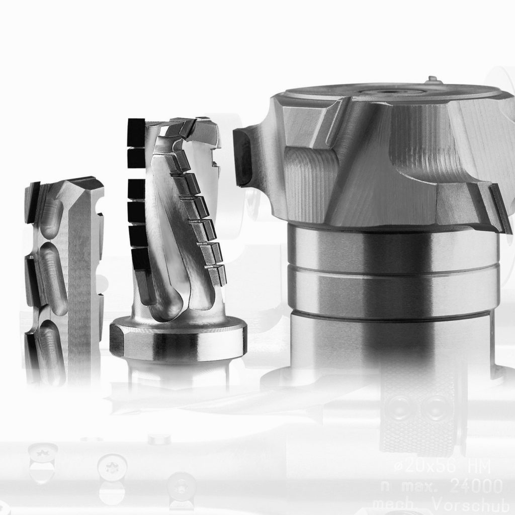
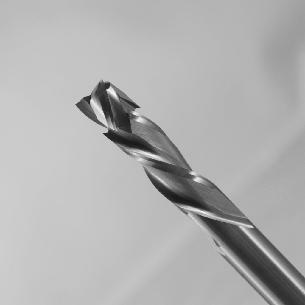
Cutting tool options Moving on to the cutting tool options, it’s important to understand that this is the wrong place to worry about initial tool cost. Accurate cutting tool cost is measured by cost per linear foot machined. Choosing the wrong tool can severely restrict and limit the machine’s capabilities and even give back some of its selling features. Accuracy, cost-effective production, superior finish quality, waste reduction and maintaining the integrity of machine and spindle all boil down to tool holder and cutting tool selection. Poor quality tool holders or out of balance cutting tools will end up costing far more than might initially meet the eye. Whether the choice is solid carbide spiral tools, insert tools, custom profile tooling or PCD (polycrystalline diamond) tooling, a close look at the pros and cons of each type is something well worth researching and understanding. One company can easily waste thousands of dollars if using ¾” 2-flute solid carbide compression bits to machine table tops, for instance, when a comparable 2-flute carbide insert compression bit will easily out-perform for a small fraction of the cost. A phenolic fabricator may go through many solid carbide bits every day when a polycrystalline diamond (PCD) bit (special design for phenolic) will run considerably longer and reduce overall machining cost. Someone purchasing a carbide-tipped round-over bit to run on a CNC machine will buy a lot more bits and never maintain uniformity, when an insert tool will maintain constant diameter and hold dimensional accuracy throughout at a lower cost.
Use tools correctly Whatever tool choice is made, the most important aspect will be using it correctly. The best cutting tool can only perform well if it is used within the parameters it was designed for. The basis of successful cutting tool performance is a synergy of machine quality/integrity, material hold-down, dust extraction, the clamping system (tool holder/collets) and tool and material composition operating under correct machining parameters. The most important point to consider with any cutting tool is the actual chip load it will generate during the cutting cycle. If the chip load is not within the ideal range for the material being machined, it will result in either overheating of the tool and very short tool life, or, pushing the tool beyond its limits resulting in tool failure (breakage). A very prominent notion is, for instance, that more flutes on a router bit will yield a better finish. This is absolutely not the case. What leads to the best cutting results is the cutting edge moving through the material at the right speed, i.e. chip load. This single factor is probably the most responsible for tool life.
Understanding chip load So, what is chip load? Simply put, it is the size/thickness of the chip being removed per flute/cutting edge with every revolution of the tool. So, going from a 2-flute bit to a 3-flute bit, the size of the chip is reduced by 33% if the feed rate is not adjusted accordingly. A smaller chip will increase the heat generated during the cut as the chips cannot be extracted out of the cut fast enough and are re-cut into yet smaller particles. Chip load charts found online or provided by tooling manufacturers should all be considered as a starting point/reference range only and it is up to the user to find the ultimate “sweet spot” that provides a combination of the longest tool life, finish and cost efficiency.
The chip load formula is as follows:
Chip Load = Feed Rate (inches per minute) / (RPM x number of flutes)
Example:
Chip Load = Feed Rate 600”/minute / (18,000×2 flutes) Chip Load = 0.017” Increasing the chip size per tooth will decrease the quality of the cut, while decreasing the chip size per tooth will shorten the tool life, so it’s important to find the ideal middle where both finish and tool life are optimum.

Cutting direction Another consideration is whether to climb cut or conventional cut. With climb cutting, the direction of the feed is identical to the direction of the cutting edge. (As an important side note, this method of cut should never be attempted with a manual fed operation as it can result in very dangerous material kick-back). Climb cutting provides a better finish quality. When conventional cutting, on the other hand, the material is feeding against the direction of the cutting edge which exerts less cutting force on the tool and increases the tool life accordingly. In summary, cutting tools and clamping systems play a paramount role in a CNC machining center delivering its promise of optimization, capacity, waste reduction and cost savings, as none of these promises can fully materialize without the contributions of high-quality tooling and accessories. Karin Deutschler, president of GUHDO USA Inc., has been selling diamond tooling since its introduction in the U.S. in 1982. You can contact her and the GDP|GUHDO team at 1-800-544-8436 or www.gdptooling.com. This article appeared in FDMC, January 2015. ©Copyright 2015, All Rights Reserved.
